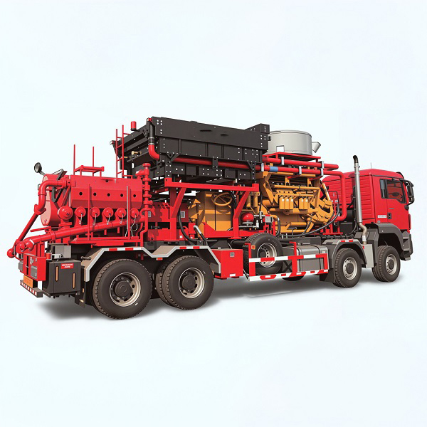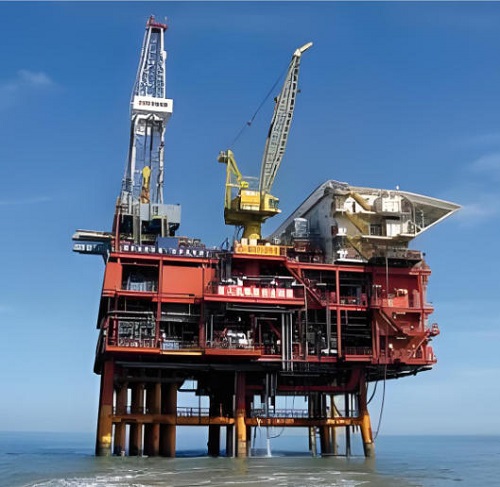
Wellhead automation technology
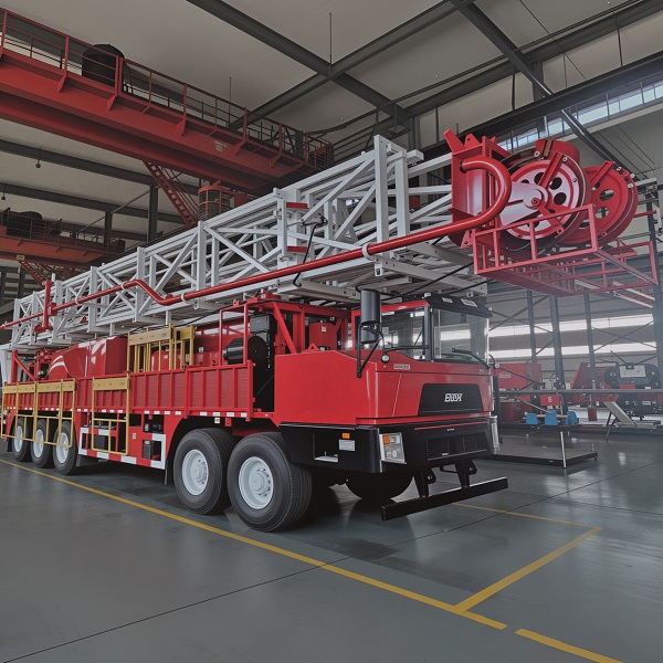
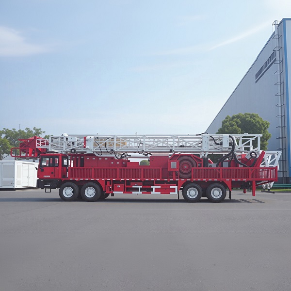
Technical Specifications – Wellhead Automation Technology
System Overview
| Component | Specification |
|---|---|
| Wellhead Standards Compliance | API Spec 6A (21st Edition), ISO 10423, GB/T 22513, NACE MR0175 |
| Safety Performance Standards | API 14C, API 14B, API 17C, IEC 61508 / IEC 61511 (SIL 2 / SIL 3) |
| Control Panel Type | Hydraulic, pneumatic, electric, or hybrid (field configurable) |
| Number of Wells Controlled | Single‑well (dedicated) or multi‑well (up to 6+ wells per master panel) |
| Power Supply | 110/220 VAC (48 V DC optional) with redundant power modules, battery backup (8+ hours) |
| PLC / RTU Type | Industrial‑grade RTU with integrated PLC functions and soft logic |
| I/O Capacity | Configurable up to 64 analog inputs, 128 digital inputs, 64 digital outputs per panel |
| Communication Protocols | Modbus RTU (RS‑232/RS‑485), Modbus TCP/IP, DNP3, IEC 60870‑5‑104, OPC UA, MQTT |
| SCADA Integration | Full integration with major SCADA platforms (Emerson, Siemens, Schneider, ABB, Rockwell) |
| Sampling Rate | Up to 10 points/second for high‑speed data logging |
| Local HMI | 7″ to 15″ sunlight‑readable touchscreen (optional) |
| Data Historian | Embedded historian with 1‑year archive (expandable) |
| Enclosure Rating | IP66 (outdoor, dust‑tight, water‑tight) |
| Operating Temperature | Standard: -20 °C to +55 °C (-4 °F to 131 °F); Arctic: -45 °C (-49 °F) |
| Working Pressure (Control Hydraulics) | Up to 20,000 PSI (138 MPa) for downhole valve control |
| Primary Valve Actuation | Hydraulic (fail‑safe close/open), pneumatic, or electric |
| Remote Access | Web SCADA dashboard via secure VPN or cellular (4G/5G) |
| Emergency Shutdown (ESD) | Automatic (pressure/temperature thresholds, fire/gas, fusible plug) + manual (local & remote) |
| Well Types Supported | Oil wells, gas wells, injection wells, water disposal wells, geothermal wells |
| API Monogram | Available upon request for API 6A components |
| Certifications | API Q1, API 6A, ISO 9001, ISO 14001, ISO 45001, CE |
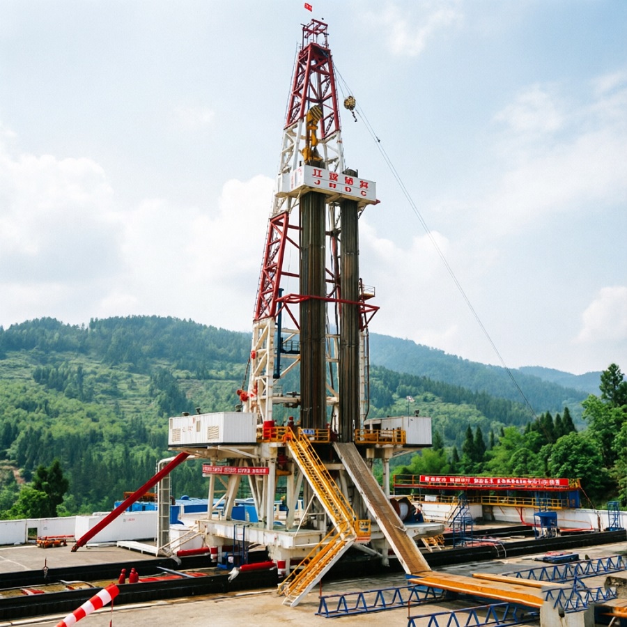
Wellhead Control Panel (WHCP) – Actuator Options
| Actuator Type | Best For | Typical Pressure Range | Fail‑Safe Mode |
|---|---|---|---|
| Hydraulic | Large‑bore high‑pressure valves, fail‑safe critical service | 3,000 – 20,000 PSI | Close on loss of pressure (spring‑return or hydraulic accumulator) |
| Pneumatic | Remote sites with compressed air, moderate pressures | 80 – 150 PSI | Close on loss of air supply (spring‑return) |
| Electric | Precise control, adjustable chokes, remote setpoint changes | N/A | Spring‑return or battery backup close on power loss |
| Solar / Off‑Grid | Remote wells without utility power | – | Integrated battery backup for autonomous operation |
Product Types – Wellhead Automation Technology Configurations
We offer a range of wellhead automation technology configurations, from basic safety shutdown to full‑field digital oilfield management.
1. Single‑Well Standalone WHCP (Basic Safety)
Best for remote exploration wells, small‑production wells, locations without communication infrastructure. A standalone WHCP installed at the wellhead provides local monitoring of pressure, temperature and flow; automatic ESD response to out‑of‑limit conditions; manual control of the SSV and wing valves; optional data logging; and battery backup. No SCADA communication is required, though communication ports can be added later.
2. Single‑Well WHCP with Remote Monitoring (SCADA Ready)
Best for wells where production data needs to be viewed from a central office, but remote control is not yet required. This configuration adds a cellular (4G/5G) or satellite communication interface to the standalone WHCP, plus a basic SCADA viewer dashboard. Operators can see real‑time well pressures, temperatures and valve status, receive email or text alarm notifications, and view historical trend charts. Remote operation of valves is not enabled at this level (view‑only). The hardware is identical to the full remote control configuration, providing a simple software upgrade path.
3. Single‑Well WHCP with Full Remote Operation & Control
Best for wells where remote shutdown, valve operation and setpoint adjustments are required from a central control room. This configuration adds secure remote access and full two‑way control capability to the SCADA dashboard. Authorised operators can view real‑time data, acknowledge alarms, change pressure or temperature setpoints and remotely command the SSV, wing valves and choke valve to open or close. All remote actions are logged with user identification and timestamp for full auditability.
4. Multi‑Well Master‑Local WHCP System (Cluster Pad)
Best for multi‑well pads (shale gas pads, cluster oil wells) where all wells share a common control room. A master panel is installed in the central equipment building, communicating with remote I/O termination boxes at each wellhead via hardened digital communication links (Ethernet, fiber optic or RS‑485). The master panel provides the operator interface and central SCADA connection. This approach reduces the number of fully featured control panels, simplifies maintenance and lowers overall cost. The system supports simultaneous monitoring and control of up to 6 wells per master panel, with multiple master panels communicating further up to a field SCADA system.
5. Full‑Field SCADA System with Distributed WHCPs
Best for oil and gas fields with dozens or hundreds of wells scattered over a wide geographic area. This is a true digital oilfield solution. Each wellhead is equipped with a smart WHCP that can operate autonomously when communication is lost. All WHCPs report to a central SCADA server (or cloud‑based SCADA platform) via secure, reliable communication links (cellular, satellite, fiber optic or radio). The central SCADA provides a unified view of the entire field with real‑time data, alarm management, reporting, historical trending, and the ability to control any well from a single workstation. The system also supports demand‑based optimisation, such as automated production cycling for plunger‑lift wells or intermittent gas wells.
6. Offshore / Onshore HPHT Wellhead Automation System
Best for HPHT wells, deep gas wells and offshore platforms requiring remote ESD. This configuration uses API 6A pressure‑class components and specially rated sensors for pressures up to 20,000 PSI (138 MPa) and temperatures up to 250 °F (121 °C). The WHCP is housed in a hazardous area (Zone 1/Zone 2) certified enclosure with explosion‑proof instrument connections. Redundancy is increased, with dual power supplies, dual communication paths and triple‑redundant safety logic (SIL‑3). The system is designed to operate in offshore environments with the appropriate environmental protection and certification (DNV, ABS, Lloyds). ESD response time is sub‑second.
7. Arctic‑Rated Wellhead Automation System (Cold Climate)
Best for fields in Siberia, northern Canada, Alaska and other regions with sustained sub‑freezing temperatures. Our arctic package extends the operating temperature range to -45 °C (-49 °F) and includes heated enclosures (electric heat tracing), low‑temperature hydraulic fluids and seals, battery heaters and oversized battery banks, insulated wiring and weather‑proofed connectors, and nitrogen‑purged instrument enclosures for high‑humidity or freeze‑thaw cycles.
Applications – Where Our Wellhead Automation Technology Excels
-
Onshore conventional oil & gas fields – Replace manual wellhead checks and paper logs with remote real‑time monitoring, automated production data collection and immediate alarm notification.
-
Offshore production platforms – Reduce personnel exposure to hazardous areas, manage wellhead safety shutdown systems and integrate with platform DCS.
-
Unconventional (shale / tight) fields – Monitor and control dozens of wells from a central pad equipment building, reduce truck rolls for well checks, and optimise production through automated plunger‑lift and intermittent well control.
-
High‑pressure, high‑temperature (HPHT) wells – Achieve safety compliance with API 6A pressure‑containing components while providing remote monitoring and automatic ESD for extremely high‑pressure wells.
-
Remote & unmanned well sites – Operate with minimal or no on‑site personnel, rely on automated safety shutdown systems, and use cellular or satellite communication for remote surveillance and control.
-
Enhanced oil recovery (EOR) / injection wells – Monitor waterflood, steam injection and gas injection wells remotely, and adjust injection rates based on reservoir response.
-
Abandoned well monitoring – Retain automated monitoring on suspended or abandoned wells to detect pressure changes or leaks, meeting regulatory surveillance requirements without routine site visits.
Why Choose SJ Petro for Wellhead Automation Technology?
Because wellhead automation is not an afterthought. It must be integrated from the start – hardware, software, safety logic, commissioning, training – with a manufacturer who builds every component.
| Your Challenge | SJ Petro’s Answer |
|---|---|
| "My wellhead equipment must meet API 6A for an international tender.” | We design and manufacture all pressure‑containing components to API 6A (21st Edition), including automatic closure requirements for loss of power, and provide the full documentation package. |
| "I need ESD logic that meets SIL 2 or SIL 3 for my offshore platform.” | Our system is designed to IEC 61508 / IEC 61511 standards, with SIL‑rated components and full documentation. |
| "I have a mix of oil, gas and injection wells on the same pad.” | Our system supports all well types with configurable control logic and the same operator interface, simplifying training and maintenance. |
| "I need remote monitoring but I am concerned about security.” | Our SCADA communication uses VPN, encryption and role‑based access controls. The WHCP maintains local control even if the communication link fails. |
| "My field is widely scattered with limited electricity.” | Our WHCPs include low‑power components (less than 50 W typical) and optional solar‑charging battery systems for off‑grid wells. |
| "I need to integrate with my existing SCADA system.” | Our WHCPs support Modbus RTU, Modbus TCP, DNP3, IEC 60870‑5‑104, OPC UA and MQTT. We also provide the IEC‑1131 programming environment to match your existing standards. |
| "I operate in an arctic environment.” | The arctic package is available with heating, low‑temperature hydraulics and extra battery capacity, field‑proven in Russia at -45 °C. |
More reasons to trust SJ Petro:
-
Sinopec Group heritage – 80+ years of oilfield equipment engineering, founded in 1941, rooted in Jingzhou, Hubei.
-
API 6A, API Q1, ISO 9001 certified – full international certification, not "designed to.”
-
In‑house manufacturing – we design, fabricate and test our own WHCPs, RTU/PLC systems and API‑certified wellhead components.
-
Global track record – wellhead equipment and control systems delivered to the Middle East, Central Asia, Russia, South America, Africa and Southeast Asia.
-
Flexible commercial terms – milestone payments, operating leases and direct financing available for qualified buyers.
Frequently Asked Questions (FAQ) – Wellhead Automation Technology
Q1: What is wellhead automation technology?
A: Wellhead automation technology is an integrated system that controls, monitors and safeguards a well. It consists of a wellhead control panel (WHCP) with a PLC or RTU, sensors and actuators, and optional SCADA remote monitoring software. It continuously measures parameters such as pressure, temperature and flow, can automatically shut in the well if setpoint limits are exceeded, and can report data and alarms to a central control room in real time.
Q2: What is a wellhead control panel (WHCP)?
A: A WHCP is the local hardware unit installed near the well. It houses the control logic processor (PLC or RTU), power supplies, operator interface, emergency shutdown buttons and valve control solenoids. It serves as the "brain” of the wellhead automation system, executing safety shutdown logic and communicating with remote SCADA servers. WHCPs are integrated systems that collect electrical, pneumatic and hydraulic circuits necessary for the control of all valves placed in the wellheads (SSV, master, wing, choke, ESD, HIPPS).
Q3: What is the difference between ESD, PSD and basic wellhead shutdown?
A: ESD (Emergency Shutdown) is the highest‑priority safety function, triggered by well‑level conditions such as high/low pressure, high temperature, fire detection or manual ESD pushbutton. It shuts down the entire well. PSD (Process Shutdown) is triggered by facility‑level conditions, such as separator high level or flare flame failure. Basic wellhead shutdown refers to routine valve closure for maintenance or workover. Our automation system includes all three types with clear prioritisation.
Q4: What API standards govern wellhead automation equipment?
A: API Spec 6A (21st Edition) governs the wellhead valves, chokes, flanges, Christmas trees and other pressure‑containing components. API 14C, API 14B and API 17C provide additional requirements for offshore safety systems and subsurface safety valves. Our system is fully compliant with these standards.
Q5: What is SIL rating, and why does it matter for wellhead control?
A: SIL (Safety Integrity Level) is defined by IEC 61508 and IEC 61511 standards. SIL 2 provides moderate protection; SIL 3 provides high‑confidence safety for applications where the risk of failure must be extremely low. For wellhead ESD, SIL 2 or SIL 3 rated components ensure that the safety function will perform reliably even when a fault occurs. Our WHCP can be specified with SIL‑rated logic solvers and sensors.
Q6: Can the WHCP be retrofitted to an existing well?
A: Yes. Our WHCPs are designed for retrofit applications. We can interface with existing API‑flanged valves and add actuator kits (hydraulic, pneumatic or electric) to automate manual valves.
Q7: What communication options are available for remote monitoring?
A: We support Modbus RTU (RS‑232/RS‑485), Modbus TCP/IP, DNP3, IEC 60870‑5‑104, OPC UA and MQTT for integration with SCADA hosts. Physical communication can be via 4G/5G cellular, satellite, fiber optic, licensed or unlicensed radio, or direct Ethernet.
Q8: Is the WHCP powered by grid electricity or solar?
A: We provide WHCPs for both. For grid‑powered locations, we use 110/220 VAC with battery backup. For off‑grid sites, we can supply a solar‑charging battery system sized for the well’s power requirements, including enough battery capacity for multiple days of autonomous operation during poor solar conditions.
Q9: What is the expected lifespan of a wellhead automation system?
A: With proper maintenance (periodic battery replacement, actuator service, software updates), our system is designed for a 10‑ to 15‑year operational life. Many of our API 6A wellhead components have field life exceeding 20 years.
Q10: Can the system support plunger‑lift or intermittent well control?
A: Yes. The RTU/PLC includes native logic functions for plunger‑lift optimisation (timed and pressure‑based operation) and intermittent well control (automated open/closed cycles based on time, production volume or reservoir pressure response). These are pre‑configured options in our software library.
Q11: What kind of training do you provide for operators?
A: For every system purchase, we provide 2–5 days of on‑site training during commissioning, covering WHCP local operations, SCADA usage, alarm handling and basic maintenance. Digital manuals, video tutorials and remote support are also included.
Q12: Can I get an API monogram on the WHCP components?
A: Yes. The wellhead valves, chokes, flanges and other pressure‑containing components can be API‑monogrammed. The control panel itself does not carry the API monogram, but it is certified to meet the functional safety requirements of API 14C, API 14B and API 17C. Third‑party witness testing (SGS, BV, DNV) is available upon request.
Q13: What documentation do you provide for regulatory compliance?
A: We provide a complete documentation package: API 6A data sheets, material test reports (EN 10204 3.1), hydrostatic test certificates, NDT reports, cause‑and‑effect matrix for ESD logic, SIL assessment certificates, electrical schematic diagrams, as‑built drawings and operation manuals.
Q14: What is the lead time for a wellhead automation system?
A: Standard lead times from order confirmation:
-
Single‑well WHCP: 6–8 weeks
-
Multi‑well master‑local system: 10–12 weeks
-
Full‑field SCADA system: 14–20 weeks
-
Custom / arctic / offshore packages: add 4–6 weeks
Expedited delivery may be available – contact our sales team.
Q15: Do you provide financing or leasing for wellhead automation systems?
A: Yes. For qualified buyers, we offer direct financing through partner banks (terms up to 5 years), operating leases (low monthly payments) and milestone payment plans (30/40/30). Contact our sales team for a lease proposal.
Q16: How does your system handle loss of communication between the WHCP and SCADA server?
A: The WHCP continues to execute its control logic and safety functions autonomously. Sensor data is logged locally to the embedded historian. When communication is restored, the SCADA server automatically retrieves the backlogged data, ensuring no records are lost. The WHCP remains capable of local ESD and control even when the wide‑area network is offline.
Q17: Do you integrate with existing wellhead valves from other manufacturers?
A: Yes. Our WHCP can interface with most major brands of API 6A gate valves, chokes and surface safety valves, provided the actuator mounting and control requirements are compatible. We can supply adapter kits and conversion assemblies where needed.